When preparing CAD models for Finite Element Analysis (FEA) or Computational Fluid Dynamics (CFD) simulations, the choice between STP (STEP) and STL file formats can significantly impact your results. While both formats can transfer 3D geometry from CAD systems to simulation software, they represent geometry in fundamentally different ways—and these differences directly affect mesh quality, preprocessing time, and ultimately, simulation accuracy.
The Fundamental Difference
The core distinction between STP and STL files lies in how they represent geometric surfaces. STP files preserve the precise mathematical definitions of curves and surfaces directly from the CAD model—whether they're planar faces, cylindrical surfaces, splines, or NURBS. This is known as a boundary representation (B-Rep) format, where geometry is defined by its exact mathematical relationships.
STL files, in contrast, approximate all surfaces using a triangular mesh—a tessellation of the original geometry. Every curve, every smooth surface, and every complex feature gets converted into a collection of flat triangular facets. While this simplification makes STL files universally compatible and easy to process, it inherently introduces geometric approximation.
Key Insight
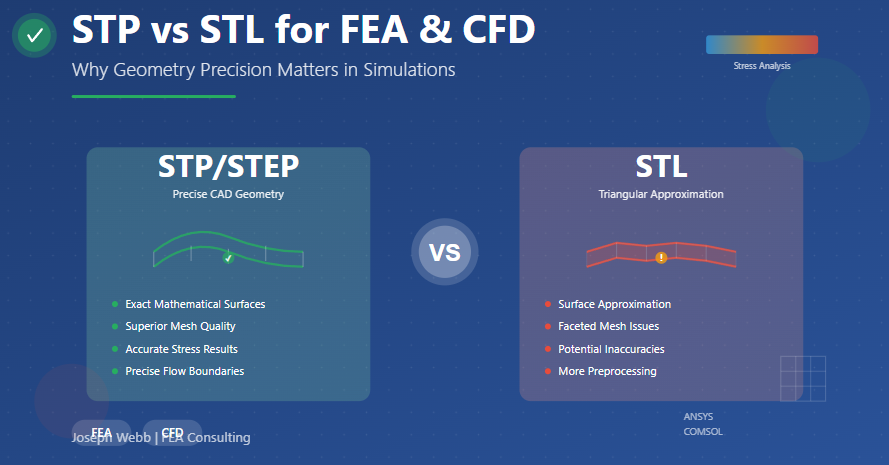
STP (STEP) files preserve precise CAD geometry including curves and surfaces, making them ideal for accurate simulations in tools like ANSYS, COMSOL, and other professional FEA/CFD platforms.
Unlike STL, which approximates surfaces with triangular meshes, STP maintains CAD integrity, reducing preprocessing errors and improving mesh quality.
Impact on FEA Simulations
Geometry Accuracy and Stress Concentrations
In structural analysis, accurate geometry is critical—especially at features that create stress concentrations like fillets, holes, and complex transitions. When you import an STL file, these smooth features have already been approximated by flat triangular facets. The faceting introduces artificial geometric discontinuities that can significantly affect stress analysis results.
Consider a fillet radius designed to reduce stress concentration. In an STP file, the fillet is represented as its true curved surface. Your meshing software can create elements that follow this exact curve, properly capturing the stress distribution. With an STL file, that same fillet becomes a series of flat facets, and the mesh must conform to this already-approximated geometry. The result? Artificial stress concentrations at facet edges and potentially misleading stress values.
Mesh Quality and Element Distribution
Modern meshing algorithms work best when they can interrogate the true geometric definition of surfaces. With STP files, the mesher knows which surfaces are planar, which are curved, and what their curvature characteristics are. This knowledge enables intelligent element placement, proper element sizing at critical features, and optimal mesh density distribution.
STL files provide no such information—the mesher only sees a collection of triangles. It cannot distinguish between surfaces that were originally planar and those that were curved. This limitation often requires manual intervention to achieve acceptable mesh quality, particularly in areas with complex geometry or high gradients.
Better Stress and Strain Results
The combination of accurate geometry and superior mesh quality directly translates to more reliable FEA results. Stress and strain calculations depend on element shape quality and accurate representation of the physical geometry. STP files enable both, while STL files compromise on the geometric foundation before meshing even begins.
For linear static analysis, the differences might be acceptable for simple geometries with coarse features. However, for nonlinear analysis, contact problems, or designs with tight tolerances and critical features, the geometric fidelity of STP files becomes essential for trustworthy results.
Impact on CFD Simulations
Accurate Flow Boundaries
In CFD, the accuracy of your flow boundaries—the surfaces where fluid interacts with solid geometry—is paramount. Flow separation, boundary layer development, and pressure distributions all depend on the precise definition of these surfaces. STL approximations of curved surfaces can introduce artificial roughness and false flow features.
Consider analyzing airflow over a streamlined shape. The smooth transitions critical to accurate drag prediction become faceted in STL format. These facets can trigger premature flow separation or create artificial turbulence, leading to incorrect predictions of forces, pressure distributions, and flow patterns.
Boundary Layer Meshing
CFD simulations often require fine boundary layer meshes near walls to capture viscous effects accurately. These prismatic or inflation layers must conform to the surface geometry while maintaining good element quality. With STP files, the mesher can create boundary layers that follow the true curved surfaces, maintaining consistent layer thickness and smooth transitions.
STL surfaces present significant challenges for boundary layer meshing. The faceted nature means boundary layers must conform to piecewise-flat surfaces, potentially creating poorly-shaped elements at facet intersections. This can lead to convergence problems or require excessive mesh refinement to achieve adequate solution quality.
Volume Mesh Quality
Whether using tetrahedral, hexahedral, or polyhedral volume meshes, the quality of elements near boundaries affects overall mesh quality throughout the domain. STP files provide the clean, well-defined boundaries that enable robust automated meshing. STL files may require extensive manual cleanup, surface wrapping, or geometry repair before successful mesh generation—particularly for complex geometries with thin features or tight clearances.
STP (STEP) Advantages
Precise Geometry: Maintains exact mathematical definitions of all surfaces and curves
Better Mesh Quality: Enables intelligent automated meshing with optimal element distribution
Accurate Results: Provides reliable stress/strain for FEA and flow boundaries for CFD
Less Preprocessing: Reduces manual geometry cleanup and repair work
Professional Standard: Preferred format in ANSYS, COMSOL, and other advanced tools
STL Characteristics
Faceted Approximation: Converts all geometry to triangular mesh representation
Universal Compatibility: Widely supported across many software platforms
Simpler Format: Straightforward file structure, easy to process
Potential Inaccuracies: Surface approximation can affect simulation results
More Preprocessing: Often requires geometry repair and manual intervention
When STL Might Be Acceptable
Simple Geometries
For models dominated by planar faces and large radii where geometric features are significantly larger than element size, STL approximation may introduce negligible error. Simple box-like structures or designs with primarily flat surfaces can often be analyzed adequately from STL files, though STP would still be preferable.
Preliminary Studies
Early-stage design exploration or rough feasibility studies where high accuracy isn't critical might tolerate STL approximations. However, any results used for design decisions or validation should be confirmed with proper geometry from STP files.
Legacy Workflows
Some older software or specialized applications may have better STL support than STP import capabilities. In these cases, using the highest resolution STL export available and carefully validating the geometric approximation becomes important.
Best Practices for Simulation Geometry
Choose STP for Precision
For professional FEA and CFD work, STP files should be your default choice. The format maintains CAD integrity throughout the simulation workflow, ensuring that the geometry you analyze accurately represents your design intent. This is particularly critical for:
- Designs with complex curved surfaces or small fillets
- Models where stress concentrations are critical
- CFD studies requiring accurate flow boundaries
- Analyses that will inform design decisions or validation
- Any work requiring professional-grade accuracy
Verify Geometry Import
Regardless of format, always verify that geometry imported correctly into your simulation software. Check for missing surfaces, inverted normals, or gaps in the geometry. For STP files, confirm that curved surfaces maintained their mathematical definitions. For STL files, inspect the tessellation quality and facet density at critical features.
CAD-Integrated Workflows
Many modern simulation platforms offer direct CAD integration or associative geometry links. These approaches bypass file export/import entirely, maintaining the highest possible geometric fidelity. When available, CAD-integrated workflows provide advantages beyond what even STP files can offer, including parametric updates and design optimization capabilities.
Software Support
Professional FEA Platforms
Industry-standard FEA tools like ANSYS, Abaqus, NASTRAN, and LS-DYNA all have robust STP import capabilities and are optimized to work with precise CAD geometry. These platforms can handle complex B-Rep geometry and include sophisticated algorithms for mesh generation from STP files.
COMSOL Multiphysics, used extensively for coupled physics simulations, also strongly favors STP format. The software's geometry engine is designed to work with CAD-quality geometry, and using STP files enables access to its advanced meshing and geometry operations.
CFD Applications
CFD codes including ANSYS Fluent, STAR-CCM+, and OpenFOAM can import STP geometry and include specialized tools for creating high-quality CFD meshes from precise CAD surfaces. While these tools can also work with STL files (often requiring intermediate surface wrapping steps), STP import typically results in more robust meshing workflows.
File Size and Performance Considerations
Storage and Transfer
STL files can become very large, particularly when exported at high resolution to minimize approximation errors. A complex CAD model might result in an STL file with millions of triangles. STP files, storing mathematical surface definitions rather than mesh approximations, are often smaller for complex geometries while maintaining perfect accuracy.
Import Speed
STL import is generally faster than STP import because the format is simpler. However, the time saved on import is often lost (and then some) in geometry repair, cleanup, and manual preprocessing required to achieve acceptable mesh quality from faceted geometry.
Making the Right Choice
The Bottom Line
For professional FEA and CFD workflows, STP (STEP) format is the clear choice. It preserves geometric precision, enables superior mesh quality, and ultimately delivers more accurate simulation results. While STL has its place in rapid prototyping and 3D printing applications, its surface approximation makes it a poor choice for engineering analysis where accuracy matters.
The slight additional complexity of working with STP files is vastly outweighed by the benefits of maintaining true CAD geometry throughout your simulation workflow. Modern simulation tools are optimized to handle STP geometry efficiently, making it the professional standard for good reason.
Professional FEA Services
Proper geometry handling is just one aspect of conducting reliable FEA and CFD simulations. Material selection, boundary conditions, mesh convergence studies, and results interpretation all require engineering expertise and experience. Working with accurate geometry from STP files provides the foundation for trustworthy analysis, but expert execution of the complete simulation workflow ensures results you can confidently use for design decisions.
Need expert FEA analysis for your project? With experience in FEMAP, NASTRAN, and other professional simulation tools, I can help ensure your analysis provides the accurate, reliable results you need for critical design decisions. From geometry preparation through mesh generation, solving, and post-processing, I deliver comprehensive simulation services tailored to your specific requirements.
Conclusion
The choice between STP and STL formats for FEA and CFD simulations comes down to a fundamental question: do you want to analyze an approximation of your geometry, or the actual geometry itself? STP files maintain the precise mathematical definitions from your CAD system, ensuring that stress concentrations, flow boundaries, and other critical features are represented accurately.
While STL's simplicity and universal compatibility have their place in manufacturing and visualization applications, the format's faceted approximation of surfaces introduces compromises that can significantly impact simulation accuracy. For professional engineering analysis where results inform design decisions, validate safety margins, or optimize performance, the geometric precision of STP files is essential.
Modern simulation software is designed to work efficiently with STP geometry, and the workflow advantages—better automated meshing, fewer preprocessing issues, more reliable results—make STP the clear choice for serious engineering analysis. When your simulations matter, start with geometry that accurately represents what you're trying to analyze.