The answer is a resounding yes—an inadequate mesh can dramatically affect the accuracy and reliability of your finite element analysis results. Whether you're analyzing structural stress, thermal performance, or dynamic response, the quality and refinement of your mesh directly determines whether your simulation provides trustworthy engineering insights or misleading predictions.
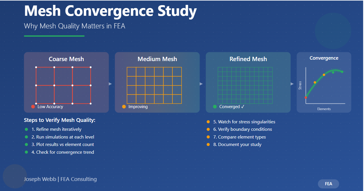
A mesh convergence study is the systematic process engineers use to verify that their mesh is sufficiently refined to produce accurate results. This critical validation step ensures that further mesh refinement would not significantly change the solution, giving you confidence that your analysis captures the true physics of the problem rather than artifacts of mesh coarseness.
Why Mesh Convergence Matters
Finite element analysis divides continuous structures into discrete elements. Each element approximates the behavior of a small portion of the structure. When elements are too large or poorly shaped, these approximations become inaccurate, leading to:
- Underestimated stress values that miss critical design issues
- Incorrect failure predictions that compromise safety
- Poor optimization results that waste material or performance
- Misleading design decisions based on unreliable data
Step-by-Step: Performing a Mesh Convergence Study
Step 1: Identify the Region of Interest
Begin by selecting the output parameter you want to validate. This might be maximum stress in a critical location, displacement at a specific point, natural frequency, reaction force, or any other quantity that matters for your design decision. Focus on parameters that will actually influence engineering judgments rather than arbitrary values.
For structural analyses, stress concentrations at geometric features like holes, fillets, or section changes are typically the most critical regions. For thermal analyses, maximum temperatures or heat flux at boundaries often drive design. Identifying what truly matters allows you to focus mesh refinement where it counts.
Step 2: Refine the Mesh Iteratively
Start with a relatively coarse mesh that captures the basic geometry but uses larger elements. Gradually decrease element size to increase the total number of elements in your model. This refinement should be systematic—common approaches include:
- Global refinement: Reducing element size uniformly throughout the model
- Local refinement: Decreasing element size specifically in regions of interest
- Adaptive refinement: Using software algorithms to automatically refine high-gradient areas
Each refinement iteration typically aims to approximately double the number of elements, though the specific factor depends on element type and geometry complexity. For 2D problems, halving the element edge length roughly quadruples element count. For 3D problems, the same edge length reduction increases element count by approximately eight times.
Step 3: Run Simulations for Each Mesh
For each mesh refinement level, execute a complete finite element analysis and carefully record your parameter of interest. Maintain identical boundary conditions, loads, and material properties across all runs—the only variable should be mesh density. This controlled approach ensures that observed changes result from mesh refinement rather than inadvertent model modifications.
Modern FEA software can often batch these analyses, but verify that solver settings remain consistent. Different mesh densities might trigger automatic solver parameter adjustments that could confound your convergence assessment.
Step 4: Plot Results and Assess Convergence
Create a plot showing your output parameter on the vertical axis against either number of elements or characteristic element size on the horizontal axis. The convergence trend should show the parameter approaching a stable value as mesh density increases. When the curve flattens—meaning further refinement produces minimal change—you've achieved mesh convergence.
Quantitatively, many engineers consider a mesh converged when successive refinements change results by less than 1-5%, though the acceptable tolerance depends on application requirements. Safety-critical aerospace components might demand 1% convergence, while preliminary design studies might accept 5% or even 10%.
📊 Convergence Indicators
Successful Convergence:
- Results stabilize with refinement
- Changes become progressively smaller
- Stress distributions become smooth
- Element quality metrics improve
⚠️ Warning Signs
Potential Issues:
- Results continue changing significantly
- Non-monotonic convergence behavior
- Stress values increasing without bound
- Poor element quality persists
Step 5: Check for Stress Singularities
Not all problems converge cleanly. Stress singularities—locations where stresses theoretically approach infinity—can prevent convergence no matter how much you refine the mesh. These singularities occur at geometric discontinuities like sharp reentrant corners, point loads, or certain boundary condition applications.
If you observe stress values continuously increasing with mesh refinement, particularly at geometric features or load application points, you may be dealing with a singularity. In such cases, the mathematical model doesn't accurately represent physical reality. Real materials have finite strength, and stress concentrations are limited by local yielding, plasticity, or other nonlinear effects.
To address singularities:
- Add small fillets to eliminate sharp corners (matching manufacturing reality)
- Distribute point loads over small but finite areas
- Evaluate stress at a distance from the singularity location
- Use stress averaging or extrapolation techniques
- Consider whether the singularity location is truly critical for your design
Step 6: Verify Boundary Conditions
Boundary conditions significantly affect convergence behavior and results accuracy. Fixed constraints that prevent all degrees of freedom at a single node create artificial rigidity that can distort nearby stress fields. Similarly, concentrated loads applied to single nodes create singularities as discussed above.
Best practices for boundary conditions in convergence studies:
- Distribute constraints over realistic connection areas
- Use appropriate constraint types (remote displacements, elastic supports)
- Apply loads over finite areas matching actual load introduction
- Verify that boundary conditions don't introduce artificial stress concentrations
- Consider whether constraints adequately represent actual supports
Step 7: Compare Element Types
Different element formulations can produce significantly different convergence characteristics. Linear elements (first-order with straight edges) generally require more refinement to achieve convergence than quadratic elements (second-order with curved edges). However, linear elements are computationally cheaper per element.
Common element type considerations:
- Linear triangles/tetrahedra: Simple and robust but require fine meshes for accuracy
- Quadratic triangles/tetrahedra: Better accuracy with fewer elements but more expensive per element
- Linear quadrilaterals/hexahedra: Good performance when well-shaped but sensitive to distortion
- Quadratic quadrilaterals/hexahedra: Excellent accuracy and performance when applicable
For many problems, quadratic elements provide the best balance of accuracy and computational cost. They capture stress gradients more accurately with coarser meshes, often making them more efficient overall despite higher per-element cost.
Step 8: Example - Cantilever Plate Study
Consider a simple cantilever plate with one edge fully fixed and a uniform pressure load on the opposite edge. Starting with a single quadrilateral element is clearly insufficient—it cannot capture bending deformation accurately. As we add more elements through the thickness and length, stress predictions improve.
For this example, peak stress might be:
- 1 element: 50 MPa (severe underestimation)
- 4 elements: 85 MPa (still significantly low)
- 16 elements: 98 MPa (approaching correct value)
- 64 elements: 101 MPa (good accuracy)
- 256 elements: 102 MPa (converged within 1%)
- 1024 elements: 102.3 MPa (marginal improvement)
Plotting these values shows clear convergence around 64-256 elements. Further refinement produces negligible changes, indicating the mesh is adequate. The analytical solution for this simple geometry would be approximately 102.5 MPa, confirming our converged FEA result.
Practical Guidelines for Mesh Convergence
How Fine is Fine Enough?
There's no universal element size that works for all problems. Instead, convergence depends on the relationship between element size and characteristic feature dimensions. As a general guideline:
- Use at least 3-5 elements across the minimum feature dimension
- Employ 8-10 elements through the thickness for bending-dominated problems
- Apply 4-6 elements around hole circumferences or fillet radii
- Consider at least 20 elements per wavelength for dynamic analyses
These rules provide starting points, but convergence studies validate whether your specific mesh is adequate.
Balancing Accuracy and Computational Cost
While finer meshes generally produce more accurate results, they also increase solution time—often dramatically. Doubling element count might quadruple solution time for direct solvers or worse for iterative solvers. For transient or nonlinear analyses, computational cost compounds with mesh density.
Efficient FEA practitioners use:
- Adaptive mesh refinement: Fine mesh only where needed
- Submodeling: Global coarse model with local refined regions
- Element type selection: Quadratic elements for better efficiency
- Symmetry exploitation: Reduce model size when geometry and loads permit
Documentation and Reporting
Professional FEA work requires documenting convergence studies. Your analysis report should include:
- Convergence plots showing parameter evolution with mesh density
- Quantitative convergence criteria and achieved values
- Mesh statistics (element count, quality metrics) for final model
- Discussion of any convergence difficulties or singularities
- Justification for selected mesh based on convergence results
This documentation demonstrates due diligence and provides reviewers confidence in your results.
Common Pitfalls and How to Avoid Them
Over-Reliance on Default Mesh Settings
FEA software default mesh settings are starting points, not validated solutions. These defaults might work adequately for simple geometries but often fail for complex models or critical analyses. Always verify mesh adequacy through convergence studies rather than trusting defaults.
Focusing Only on Peak Stress
While maximum stress often receives the most attention, check convergence of other relevant parameters too. Displacement, reaction forces, and stress distributions in various locations might converge differently. Comprehensive convergence assessment examines multiple outputs.
Ignoring Element Quality
Element count alone doesn't guarantee good results—element shape quality matters too. Highly distorted elements with extreme aspect ratios or severe warping produce inaccurate results regardless of mesh density. Most FEA software provides element quality metrics; review these and remesh poorly-shaped regions.
Inconsistent Boundary Conditions
When refining meshes, ensure boundary condition application remains consistent. Loads or constraints inadvertently applied to different nodes or surfaces between mesh versions can produce apparent "convergence" that's actually just inconsistent modeling.
Professional FEA Services
Proper mesh convergence studies require more than just software skills—they demand engineering judgment about what parameters matter, understanding of FEA theory, and experience recognizing problematic convergence behavior. Whether dealing with stress singularities, interpreting non-monotonic convergence, or balancing accuracy against computational resources, expert FEA analysis ensures reliable results you can trust for critical design decisions.
Need expert FEA analysis with properly validated meshes? With extensive experience in ANSYS, NASTRAN, and advanced meshing techniques, I deliver analyses with documented convergence studies that demonstrate result reliability. From geometry preparation through mesh generation, solving, post-processing, and comprehensive reporting, I provide FEA services you can confidently use for design validation and optimization.
Contact Me for Expert FEA Analysis
Conclusion
A wrong mesh absolutely can—and often does—impact simulation results. The difference between an inadequate mesh and a properly converged one can mean the difference between a safe, optimized design and a catastrophic failure. Mesh convergence studies are not optional extras for cautious engineers; they're fundamental validation steps that separate reliable analysis from speculation.
By systematically refining your mesh, monitoring result changes, and applying engineering judgment about acceptable convergence criteria, you ensure that your FEA delivers trustworthy predictions. Whether you're designing aerospace structures, optimizing automotive components, or validating consumer products, the time invested in proper convergence studies pays dividends in confident, reliable engineering decisions.
Remember that FEA is a tool for engineering insight, not just colorful stress plots. Converged meshes provide the foundation for that insight. Take the time to verify your mesh, understand convergence behavior, and document your validation process. Your designs—and the people who depend on them—deserve nothing less than properly validated analysis.